Using Router Guide Bushings
Guide Bushings can allow you to use plunge cutting router bits as if they had bearings. In this short PDF, I explain how to figure the "offset" and give some tips.
Back Yard Pergola by Ralph Bagnall
Ralph Bagnall designed and built a shady pergola for his back yard a few years ago. When he built it, he took lots of photos so that he could share how he constructed it and how it all went together. Ralph built this great backyard feature in just a few days with common tools.
Over the Memorial Day weekend in 2011, I built a pergola for our backyard patio. The patio is a large area of cement off the driveway, but gets direct sunlight all day long so it was largely unusable.
I had a number of 2x8s left over after tearing down a decorative bridge on my property, so we decided to use them as the basis for our pergola.
Step one was preparing the posts. I notched two faces of the 4x4s to provide a shoulder for the cross beams to sit on.
The notches are 1 inch deep and 7 inches long, the same as the cross beams (although they are called 2x8s, they actually measure 1-½” x 7”).
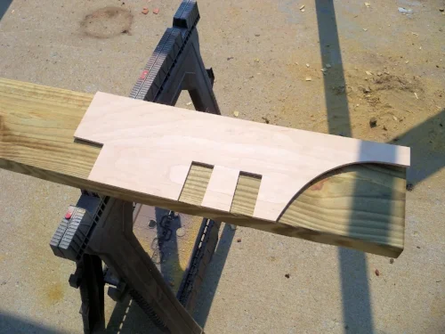
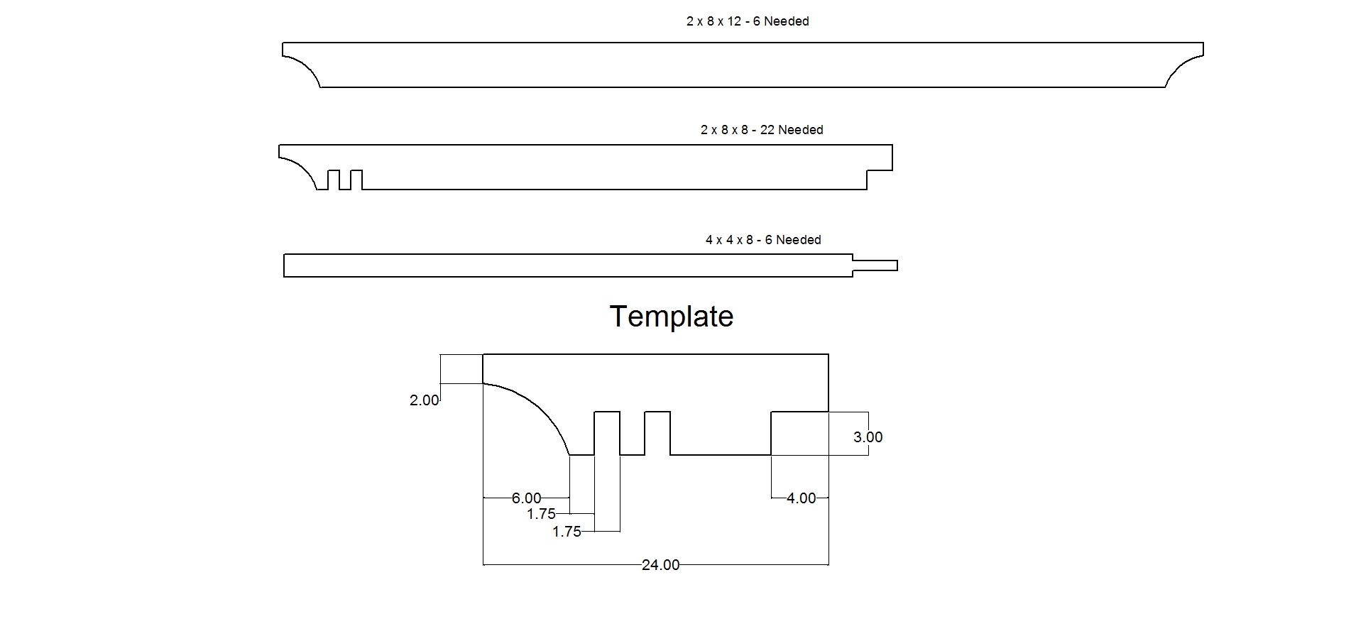
Now the cross beams needed to be prepped. I wanted a clean and even look to all the beams so I created a template to mark out the decorative end cuts as well as the notches for the upper beams. For the cross beams, I only cut the decorative cove at each end of the beam.
Two 12 foot cross beams were clamped onto each post and bolted together. This creates the three ‘arches’ that form the base of the pergola.
The ‘arches’ are connected by the 8 foot long upper beams. Four of these needed to be prepared before setting the uprights. The template was again used. Each upper beam got one end with the decorative cut and two notches to fit over the cross beams. The other end got a simple notch to overlap the center cross beams.
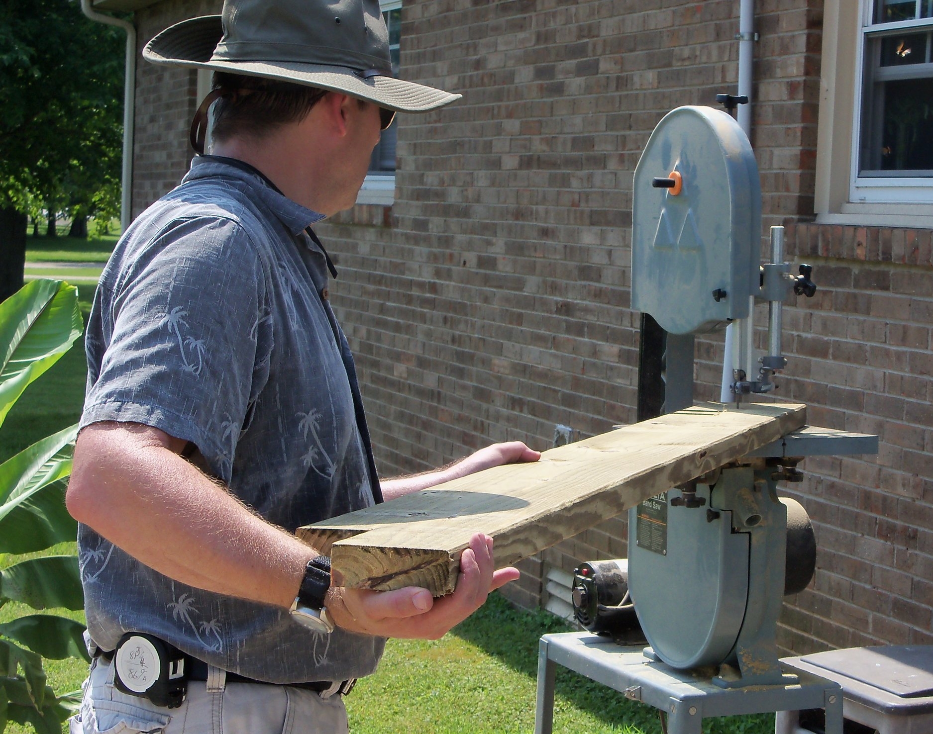
Although the decorative cove cuts can easily be made using a corded jigsaw, my jigsaw is cordless, so I used my bandsaw to cut the decorative coves. I then cut the notches with my circular saw, finishing up the cuts with a handsaw. Finally, 5/16” holes were drilled through the upper beams at all three notches for bolting them down.
Upper beams were set into each corner to tie all the uprights together, and 6” lag bolts were used to secure the upper beams to the cross beams. The structure was now self-supporting, but braces are needed to stiffen the legs.
I cut eight braces to stiffen the structure. One on each side of the center legs, and one on each corner leg.
Angle braces were also added running from the corner posts up between the cross beams and bolted into place. Now the structure was stiff enough to continue working on.
I had laid out the spacing so that the upper beams were about 12” on center, and continued cutting and bolting them in place.
Pergola Parts (Download PDF)
Flat boards were added on top of the cross beams on each side to mount the shades to. We purchased exterior roll-up shades from Home Depot and hung them across each opening. The pergola is oriented roughly North to South (as the upper beams run) so the sun comes in through the ‘sides’ in the morning and afternoon.
After finishing the pergola, I realized that the upper beams, at 12 inches on center, really don't provide enough shade with the summer sun overhead. I decided to add pressure treated lattice to the top of the pergola to provide more shade. I used what Lowe's calls ‘Privacy Screen’ as the gaps between the lattice are smaller. This has proved to be very shady and cool, even at noon with the temperatures above 100 degrees.
Problems in Furniture Making by Fred D. Crawshaw
Written as a school primer, Problems in Furniture Making by Fred D. Crawshaw poses a series of woodworking projects at levels from elementary to advanced /high school. This book contains an excellent array of useful furniture making projects that we are very pleased to be able to share with you!
Fred D. Crawshaw's 1912 book, Problems in Furniture Making, is a treasure-trove of mission and craftsman-style furniture. We have selected quite a few excerpts from this excellent volume covering a wide variety of projects. Most contain two or more projects (e.g. Plant Stand and Taboret contains plans for a Taboret and for a Plant Stand, rather than a combined single unit).
Screen Plan Drawing from Problems in Furniture Making by Fred D. Crawshaw
Download the Telephone Table PDF (1 MB)
Download the Tea Table and Screen PDF (403 KB)
Download the Taborets PDF (278 KB)
Download the Shoe Shine Table PDF (322 KB)
Download the Bench and Stool PDF (303 KB)
Download the Plant Stand and Taboret PDF (334 KB)
Download the Bookcase and Umbrella Rack PDF (277 KB)
Download the Magazine Racks PDF (280 KB)
Download the Plate Shelves PDF (350 KB)
Download the Three Chairs PDF (412 KB)
Download the Sewing Screen and Wall Cabinet PDF (283 KB)
Download the Library Table and Desk PDF (296 KB)
Download the Music Stand and Library Chair PDF (774 KB)
Download the Writing Desk and Bookcase PDF (381 KB)
Download the Wall Cabinet and Sewing Cabinet PDF (303 KB)
Download the Cabinet Stool and Umbrella Rack PDF (288 KB)
Download the Two Very Nice Hall Benches PDF (292 KB)
Download the Two Hall Stands PDF (340 KB)
Working Drawings of Colonial Furniture by Frederick J. Bryant
Frederick Bryant's Working Drawings of Colonial Furniture, published in 1922, is a wonderful tome chock-a-block full of drawings and instructions for reproducing colonial-style furniture. We have selected a variety of his table projects for your personal use.
Published in 1922, Frederick Bryant's Working Drawings of Colonial Furniture is a rare find as it contains no mission-style furniture! Beautiful photographs and drawings accompany each set of instructions.
Working Drawings of Colonial Furniture by Frederick J. Bryant
Download the Gate Leg Table PDF (2.8 MB)
Download the Sheraton Card Table PDF (1.2 MB)
Download the Sheraton Work Table PDF (1.9 MB)
Download the Sheraton Breakfast Table PDF (1.2 MB)
Download the Tavern Table PDF (1.1 MB)
Download the Tilting Tea Table PDF (1.3 MB)
Download the Hepplewhite Work Table PDF (1.1 MB)
Download the Hepplewhite Card Table PDF (1.3 MB)
Download the Empire Card Table PDF (1.6 MB)
Learn to Make Your Own Plans
Have you ever wondered how to design custom plans based on an existing plan or drawing? Ralph Bagnall uses Paul Otter's drawings and descriptions of a serving tray and stand set from his 1914 book, Furniture for the Craftsman, to walk you through how to create your own plans for this useful serving set.
Working with isometric drawings from Paul D. Otter's 1914 book, Furniture for the Craftsman, Ralph Bagnall discusses how to take this information and develop a set of shop drawings that can be used to make the serving tray and stand from the book.
I often come across plans or drawings that are the basis for a project I would like to make, but the design, size or materials aren't quite what I'm looking for. Over the years, I have learned to create custom plans to suit the end result I want. Although getting started seems a bit daunting, not to worry - I’ll break the process down into simple steps, making the task much simpler!
In his book Furniture for the Craftsman, Paul Otter provides a number of dimensions in his drawings and project description. First, we need to review them and decide if and how we will alter them to suit our project needs. Otter describes the tray as "...a mitered frame 16 x 25 in." WOW! That’s a big tray. In a smaller room, or for a petite host, that size might prove overwhelming, so now is the time to decide an appropriate size for your tray.
Creating a mock-up is a great way to get a feel for a project’s size. To create your mock-up, cut a piece of cardboard to the dimensions specified (16 x 25 inches) and see how it works in the area the tray will be stored or displayed. Trust your own sense of proportion and cut it down until the size is appropriate for the space. Another thing to take into consideration is that a large tray filled with drinks may weight quite a lot, so in this case bigger may not be better!
Tray Cutaway View by Paul Otter
In my dining room, a 16 x 25 inch tray would be out of scale, so I decided on 14 x 22 inches.
With the overall tray size in hand, we can determine the stand dimensions. The author is using 1-1/4" wide molding to frame the tray. Because the stand fits completely under the tray, his must be somewhere around 13-1/2 x 22-1/2 inches to allow the molding clearance all the way around.
Tray Molding Profile
I have chosen to keep the same molding width because if it is much smaller the joints may be weak, so my stand will measure 11-1/2 x 19-1/2 inches.
Next, we turn our focus to the stand height. Otter clearly specifies a stand height of 27" with a nominal tray thickness of 1/2" where it sits atop the stand. Since this set is designed to be set up in one area and the tray carried to guests elsewhere, it needs to be at a comfortable lifting height. Examine some of the tables around your house. A side table at 24" seems a bit low to me, but a dining table at 30" seems too high. 27 looks to be about right, but do not hesitate to alter it if needed. Standing upright, the user should be able to grasp the handles with their arms slightly bent. If you are creating this for a host or hostess who is particularly tall or short, the stand height should be increased or decreased as appropriate. If you are making a stand for a child's tea set, it will need to be even shorter!
With tray dimensions decided, the tray frame profile can be selected. I chose to stick close to the original plan for my table; a simple ogee molding easily made with a panel raising bit such as Rockler's #38665 or Freud’s #99-520. Note that the cross-section of the molding also includes a 1 degree angle cut on the outer edge and a 3/8" square rabbet for the tray bottom on the inside edge.
Next, draw up the plan for the tray. It’s not necessary to go into too much detail here. A cross section of the molding with notes about the details (10 degree angle, 3/8" square rabbet, etc.) and a plan view showing the tray frame are all that is needed. Here are my tray plans. Note the dashed lines that indicate the profile details below the visible plan view.
The original drawing shows a flat table top that is the same size as the tray. I want my table top to be just a bit smaller than the rabbeted section of the tray. This way the tray lips over the table top, helping to prevent it from accidentally sliding off. Therefore, the overall top of my table needs to be 12 x 20 inches. It would be perfectly acceptable for the table to be an open frame with no solid top (like a butler's tray stand) but since a drawer is present, a solid top is necessary. For ease of carrying, the top should overhang the frame of the table, so we can now determine the frame dimensions.
The next drawing to create is the plan (top) view of the stand. First, we need to decide on the leg size. Our original print shows 1-3/4" square legs. I think that seems rather heavy for a small table, and because I scaled down the tray, I will scale the legs down too. Here again is a good opportunity to cut some cardboard mock-up pieces to help decide on size. Mine have been scaled down to 1-1/2 inches.
With the stand top at 12 x 20 inches, and allowing for an overhang of 3/4 inches all around, the stand frame should be 10-1/2 x 18-1/2 from outside to outside. Lay this out, then decide on the apron thickness as well. If traditional mortise and tenon joints are to be used, the tenon length needs to be added to the stretchers and aprons. Floating tenons negate that need.
Here are elevation drawings of the tray and stand based on the work we have done so far.
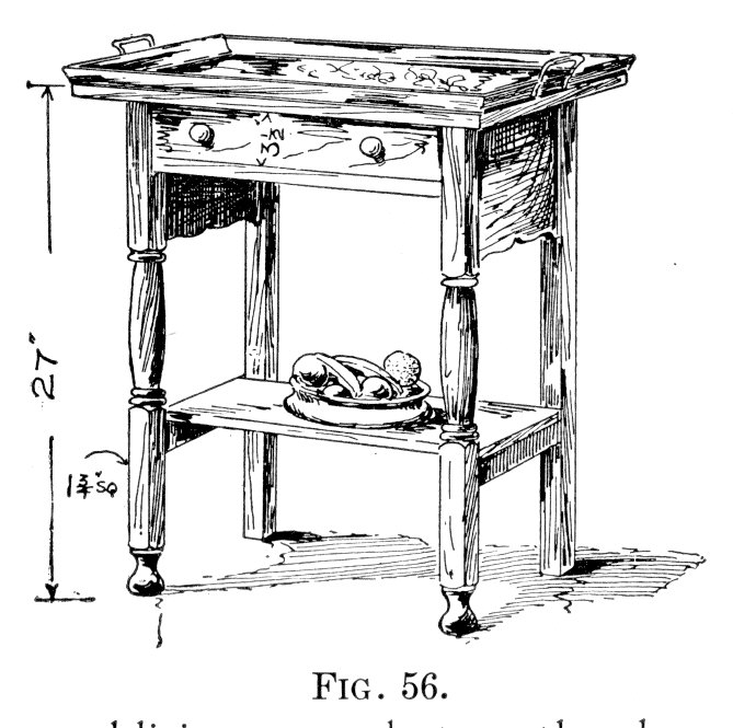
The first parts to be drawn are the front legs, so this is when you need to lay out the turned sections. The top and lower sections are left square, as shown in the original isometric view (Fig. 56).
Serving Tray and Stand from Furniture for the Craftsman by Paul Otter
The table is 27 inches tall, so the legs divide into three basic sections of 9 inches each. As there are bun feet turned at the very bottom, and the top takes up three quarters of an inch, adjustments are made to each section to balance out the overall leg. Again, this is where a mock-up helps to figure out dimensions. Having a full-scale mock-up of the leg will also be useful when it comes time to turn the legs on the lathe.
Otter’s original drawing shows the lower shelf sitting on top of the lower stretchers. Although I wanted to create a piece that closely matches the original sketch, I did ultimately decide to alter the lower shelf. It’s okay as designed, and it does avoid cutting a few mortise and tenon joints, but looks less finished and not as strong as I’d like. I chose instead to set the lower shelf into the stretchers, making the shelf another stretcher and bracing the legs from side to side. Doing this also traps the shelf top and bottom, preventing it from cupping over time.
Another change I made was the design of the rear legs. It’s common among antique tables for the front legs to be designed with greater detailing than the back legs because the back legs of most tables remain against a wall and are pretty much unseen. As this is a serving stand rather than a table, it’s likely that it will be placed convenient to the dining table and not against a wall. If the front legs were fluted, reeded, or carved, I may well have chosen to keep the rears legs plain, but as the turning is fairly simple, I decided to turn all four.
Now that the basic plans are laid out, a materials list can be created. The list not only organizes your cutting and milling steps, but also helps you determine joinery details and find flaws.
The materials list is also your shopping list. We know we need four legs from thicker stock, and a fair amount of 4/4 stock for the shelf, top and aprons.
Tray Stand Materials:
- Tray Molding: 84" x 1.25 x .75
- 4 legs at: 1.5 x 1.5 x 26.25
- Stand Top: 12 x 20 x .75
- Lower Shelf: 7 x 16.25 x .75
- 2 Front/Back Aprons: 5 x 17 x .75
- 2 Side Aprons: 8.5 x 9 x .75
- 2 Lower Stretchers: 1.25 x 9 x .75
Don’t forget to consider every part. Drawer parts, knobs, drawer runners, hardware and fasteners all need to be decided upon and detailed in the materials list. Any parts that are irregularly shaped, like the apron sides, should be drawn out in scale to help you decide if they can be cut from a single board or glued up from smaller parts. This layout will also provide the template for cutting the shapes during assembly.
In our materials list, the drawer sides, back and runners still need to be decided, (keep in mind that the drawer front is cut from the front apron) and hardware specified. Once they are added, your materials list is finished.
You have just completed your first set of plans. Congratulations!
Furniture for the Craftsman by Paul D. Otter
Paul D. Otter's book, Furniture for the Craftsman contains a myriad of unique and useful projects. We have posted excerpts of the book covering projects such as settle tables, a writing table, a dressing table, a hanging plate rack, a sewing stand, and more.
Paul Otter's 1914 "Furniture for the Craftsman" is a treasure trove of information. In addition to the project excerpts we list below, we have created a separate page dedicated to creating the serving tray he describes in this book in our Learn to Make Your Own Plans segment.
Download the Reading Table PDF (498 KB)
Download the Writing Table PDF (964 KB)
Download the Dressing Tables PDF (824 KB)
Download the Settle Tables PDF (1.9 MB)
Download the Sewing Stand PDF (299 KB)
Download the Tea Cart PDF (3 MB)
Download the Telephone Table PDF (397 KB)
Download the Hanging Plate Rack PDF (840 KB)
Practical Cabinet Maker and Furniture Designer by Fred Hodgson
In this excerpt from Fred Hodgson's Practical Cabinet Maker and Furniture Designer, Mr. Hodgson outlines how to make a revolving bookcase, including materials and drawings relevant to the build.
One of the more interesting items in Fred Hodgson's Practical Cabinet Maker and Furniture Designer, this revolving bookcase is reminiscent of the type installed in almost every small town library in America. This five-page sampling from the book is a practical how-to and includes diagrams and drawings.
Hand Work in Wood by William Noyes
Craftsmen in the early 20th century relied almost exclusively on hand tools to complete their work. An important part of nearly any woodworking project was certainly the joinery. We share Noyes illustrations of 75 common joints in use in the early 1900s.
William Noyes' 1910 book, Hand Work in Wood, is a wonderful record of woodworking in a time when there were few power tools in use and most woodworking was still painstakingly done by hand.
He includes 75 illustrations of joints commonly used by craftsmen at the time. We have scanned them for you to view and keep as a reference.
Download the Common Joints PDF (771 KB)
Home Furniture Making by G.A. Raeth
We have selected three beautifully illustrated project plans with an eye toward practical use in the home from this little book by G.A. Raeth. Written in 1910, these plans are in interesting glimpse into household furniture needs at the turn of the 20th century.
A small book of Mission Style plans from 1910 written by G.A. Raeth. Raeth includes beautiful drawings, descriptions and materials lists.
Mission Writing Desks PDF (2.7 MB)- Two separate versions of a mission-style writing desk are included.
Room Screens PDF (583 KB) - Three different room screen designs are illustrated and described.
Hall Trees PDF (5.4 MB) - Raeth includes designs for three different takes on a traditional hall tree.


